Types of Machining Processes: Turning, Milling, and Drilling
What is Machining?
In a previous blog, we focused on the future of 3D printing, also known as additive manufacturing. Additive manufacturing requires stacking layers upon layers of material to form a 3D object. Machining is another method of producing the same object. Instead of adding material, removing material achieves the desired form. You could say 3D printing is like laying bricks while machining is like sculpting.
In machining, several operations occur in a planned sequence to achieve the best results. We cover three of the most common operations including turning, drilling, and milling. Machining is a very common and versatile manufacturing process. Thus, it’s possible to machine various types of material using these three methods. Metals, plastics, composites, and wood are all possible workpiece materials.
Table of Contents:
Machine Tooling
What is Turning?
What is Drilling?
What is Milling?
Machining Innovations
Machine Tooling
Types of Machine Tooling
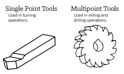
Single point tools -
- Turning Process: This type of tool rotates a workpiece while the cutting tool moves in a linear motion. This process can either be done manually or automatically
Multi-point tools -
- Drilling Process: Tool creates or refines round holes in a workpiece. This is usually done through a rotary tool with two or four helical cutting edges
- Milling Process: This type of tool creates designs by removing material from the working piece by rotating a cutting tool
Single Point vs Multi-point Tools
The desired form of the material will determine what type of tools you’ll need for the job. The two basic types of cutting tools are single point and multi-point tools. Use single point tools for turning, boring, and planing. Use multi-point tools for milling and drilling. It is imperative to properly use and maintain the cutting tools for quality purposes. Unfortunately, proper upkeep of machinery and tooling is where it can get costly.

Tooling is available in a variety of materials. The most common are carbide and high-speed steel. You may choose to use high-speed steel (HSS) for general purpose milling. But, opt for carbide to machine tougher and harder tool steels.
Cutting Speed, Feed Rate, Depth
Cutting speed, feed rate, and depth of cut are all parameters to consider when machining. The workpiece material, tooling material, and dimensions will influence these parameters. Cutting speed refers to how fast the cutting tool cuts into the workpiece material. It’s measured in surface feet per minute. Cutting feed refers to how fast the workpiece moves across its axis toward the cutting tool. It’s measured in inches per minute.
Speeds and Feeds Calculators
Turning Speed and Feed Calculator
Drilling Speed and Feed Calculator
Milling Speed and Feed Calculator
Like artistic sculpting, the workpiece first undergoes one or more roughing cuts. Their purpose is to get as close to the finished shape and dimensions as possible. After the roughing phase, a finishing cut is applied to achieve final dimensions, tolerances, and surface finish. Finishing cuts are typically done at low feeds and depth. Applying cutting fluid during both cutting phases cools and lubricates the cutting tool.
Machine Turning
Turning involves rotation of the work piece while the cutting tool moves in a linear motion. This results in a cylindrical shape. A lathe is the machine of choice for all turning operations.
Like most machining operations, turning is either done manually or automatically. The downside to manual turning is it requires continuous supervision. Automatic turning does not. With Computer Numerical Control, or CNC, you program all the movements, speeds, and tooling changes into a computer. These instructions then get sent to the lathe for completion. CNC allows for consistency and efficiency of high production runs.
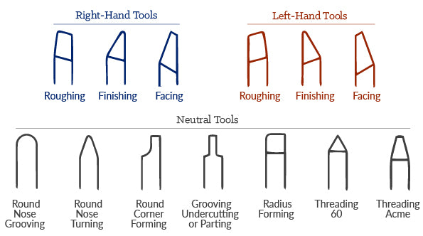
Single point cutting tools used in turning come in various shapes. They’re placed at different angles for a variety of outcomes.

Turning Speed and Feed Calculator
Machine Drilling

Drilling creates a round hole in a workpiece. A drill press or tapping machine is designed for drilling, but this process can also be performed using a milling machine. Chips are the bits of waste metal produced when machining a workpiece. The shape of the drill bit helps chips fall away from the workpiece, keeping the workpiece free of debris.
Placing the drill bit perpendicular to the workpiece reduces drifting or leading-off. For even more precision, a center drill operation is often added before drilling. Some drilling operations need angular drilling. Angular drilling requires special work-holding tooling. Other options include: rotation of the head on a manual machine or use of multiple axis’ on a CNC machine.
Ways to prevent drifting include:
- Casting/molding/forging a mark
- Center punching
- Spot drilling/center drilling
- Spot facing
Like with turning operations, different drill bits exist for specific drilling operations. Below are a few special drill bits along with their specific uses.
- Spotting Drills – short drills used to create shallow or pilot holes. If using a longer drill for these shallow holes it could have a tendency to drift.
- Peck Drilling – frequent retracting of the drill helps to clear chips from the workpiece and prevent drifting.
- Screw Machine Drills – these drills are short and can create straight and accurate holes without the need for prior spotting.
- Chucking Reamers – used to enlarge previously drilled holes to very precise diameters.
Drilling Speed and Feed Calculator
Milling Process

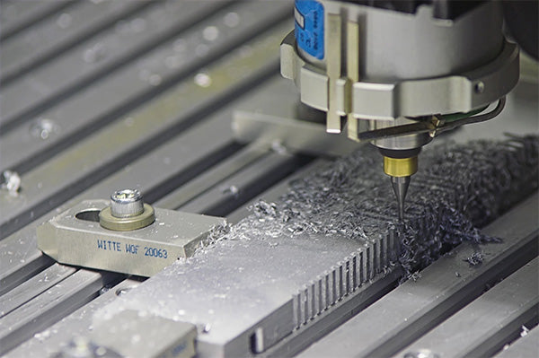
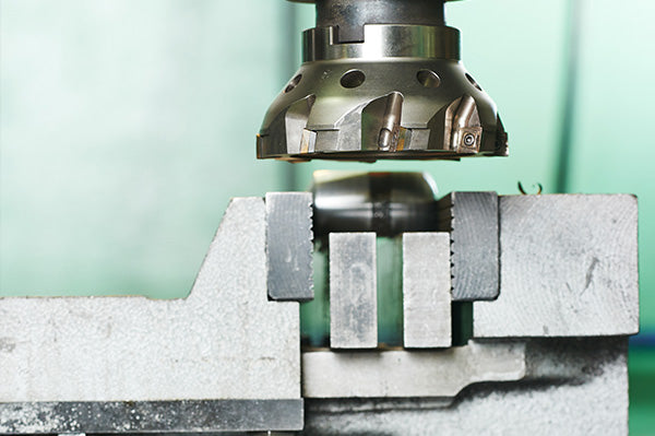
Milling operations involve using multi-point rotary cutters to remove material from a workpiece.
There are two main types of milling operations: face milling and peripheral milling. Face milling cuts flat surfaces into the workpiece and flat-bottomed cavities. The feed can be either horizontal or vertical. Peripheral milling cuts deep slots, threads, and gear teeth.
The workpiece can be fed into the cutting tool in either of two ways. Conventional milling involves feeding the workpiece against the cutter rotation. This is the recommended method for manual milling machines. Climb milling, on the other hand, feeds the workpiece in the same direction as the cutter rotation. This is the preferred method for CNC milling.
Milling is best applied as a secondary process to an already machined workpiece. It helps to define features and serves as a “finishing coat”. Use milling as a secondary process to add features such as holes, slots, pockets, and contours.
Milling Speed and Feed Calculator
Machining Innovation
There’s a lot that goes into machining a perfectly smooth, precise, functional workpiece. It requires great attention to detail and experience. Turning, drilling, and milling are just a few of the most common machining processes. They’ve been around for many, many years. Fortunately, with the development of CNC, machining has improved immensely. While conventional machining still has its purpose in manufacturing, CNC machining takes the lead. It helps facilitate large production runs with consistency and efficiency. If you’re interested in keeping up with the latest innovations and news, American Machinist is a great resource.
With 20+ years as a manufacturing solutions provider, we’re confident in our ability to draft a custom solution to fit your needs. Still have questions? Feel free to reach out and send us a message or an RFQ.
